Mechanical Engineer · CAD / FEA / CFD

Burak Brooke
Karabillioglu

Mechanical Engineering graduate from Ontario Tech University. I take projects from first CAD concept through simulation to working physical hardware — structural FEA, CFD, rapid prototyping, machining and robot programming.

Based inOshawa, ON
RelocationOpen to relocating
EIT eligibilityAll provinces
DegreeB.Eng. Mechanical
01

Selected projects

P.01 — CAPSTONE · 2025–2026 · TEAM OF 5

Autonomous Pool Skimmer Robot

End-to-end mechanical design, simulation, fabrication & testing

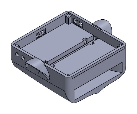
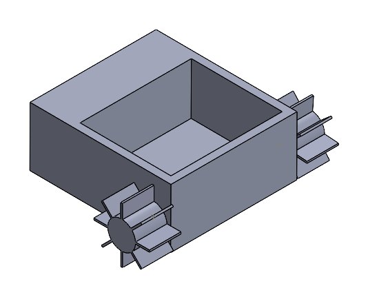
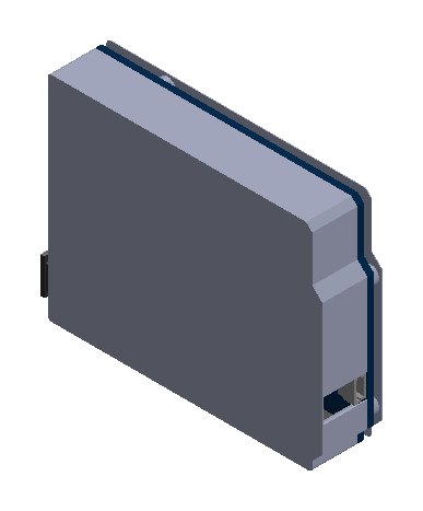
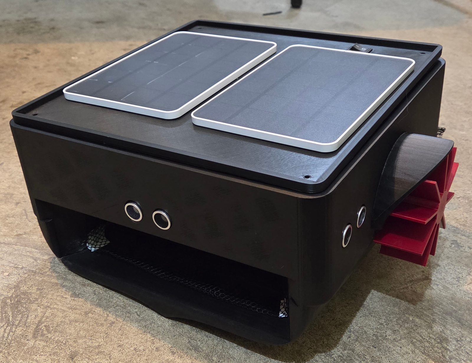
A compact, solar-assisted surface robot that autonomously skims floating debris from residential pools. Over two terms the team took it from concept sketches and a QFD through CFD hull optimization, FEA of every printed part, full engineering drawings, and a waterproofed prototype tested in water.

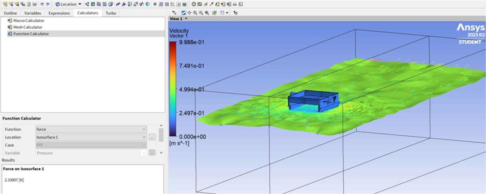
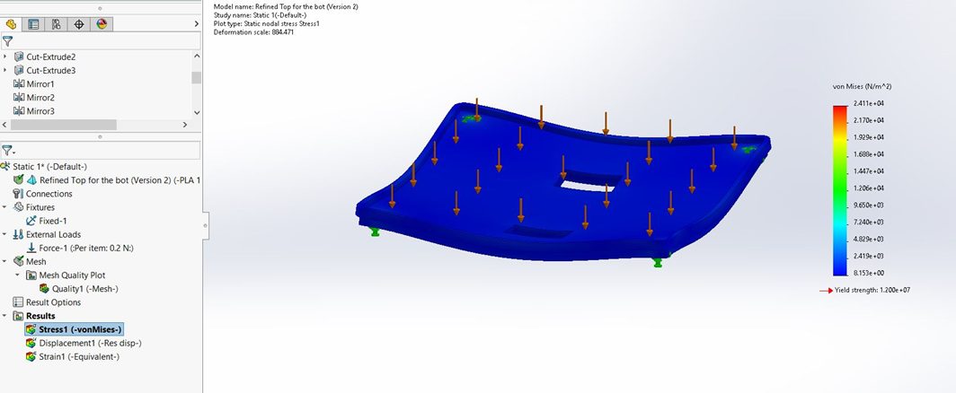
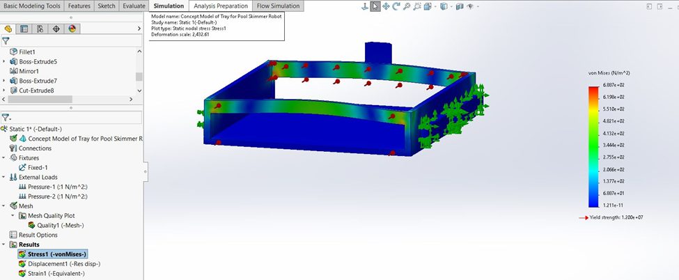
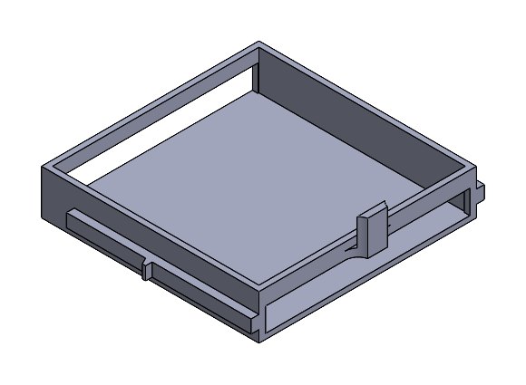
The hull was refined over seven CAD versions; each was run through ANSYS CFD at 0.5 m/s with an 0.08 m waterline, and the final hull reached a drag coefficient of 0.121 — about 19% lower than the original concept. All PLA components (hull, upper housing, paddle wheels, motor mounts, basket) were checked in SolidWorks Simulation using slicer-derived 15%-infill material properties.

SolidWorksANSYS CFDSolidWorks SimulationMATLABFDM printingArduinoGD&T drawings
  • PropulsionTwin paddle wheels on 6 V geared DC motors, differential steering
  • Sensing3× HC-SR04 ultrasonic, MPU-6050 IMU, HC-06 Bluetooth
  • PowerTriple 18650 pack with solar-assisted charging, sealed compartment
  • BuildFDM-printed PLA, acrylic-sealed; ≈ CAD $306 in materials
  • ModellingMATLAB paddle-thrust, buoyancy and odometry simulations
0.121Final hull drag coefficient
7Hull versions simulated in CFD
0.53 m/sTop measured speed in water
2 hrsIn water with a dry enclosure (< 1% mass gain)
Completed pool skimmer prototype with solar panels
FIG 1.1Completed prototype — solar panels on the sealed lid
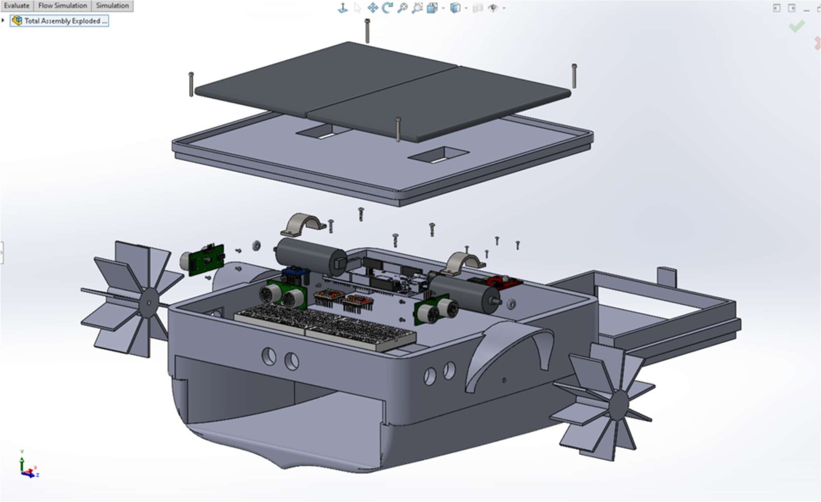
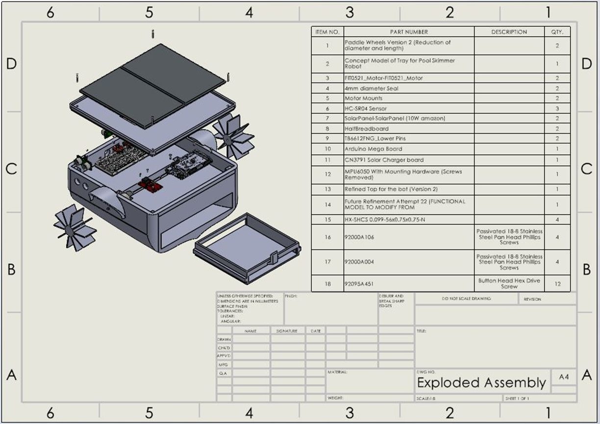
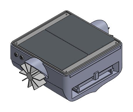
SolidWorks exploded assembly
FIG 1.2Exploded assembly — SolidWorks

Hull drag coefficient by CAD version

ANSYS CFD · 0.5 m/s · 0.08 m waterline
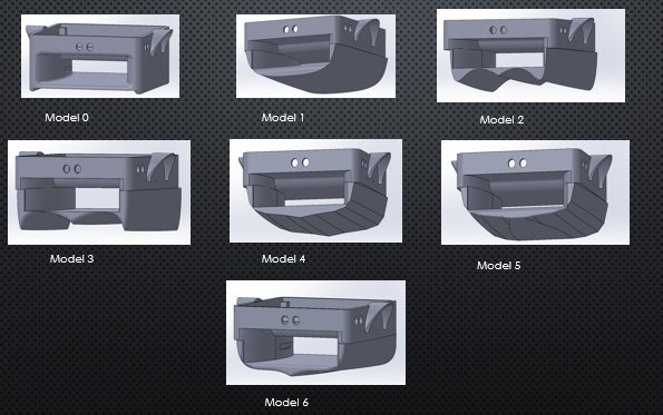
Seven hull body models compared
FIG 1.3Hull models 0–6 compared in CFD
ANSYS CFD of the chassis
FIG 1.4CFD flow around the hull — ANSYS
FEA of hull body
FIG 1.5FEA of the PLA hull body
FEA of debris basket frame
FIG 1.6FEA of the debris basket frame
Exploded assembly drawing with BOM
FIG 1.7Assembly drawing & BOM
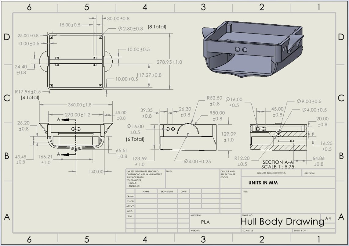
Hull body engineering drawing
FIG 1.8Hull body drawing
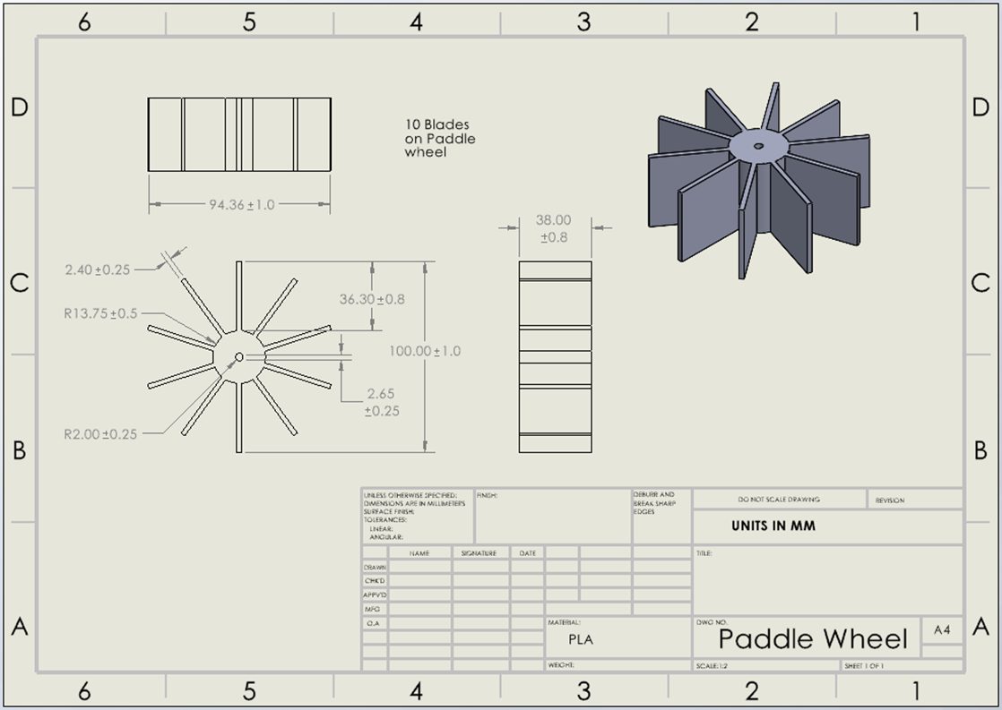
Paddle wheel engineering drawing
FIG 1.9Paddle wheel drawing
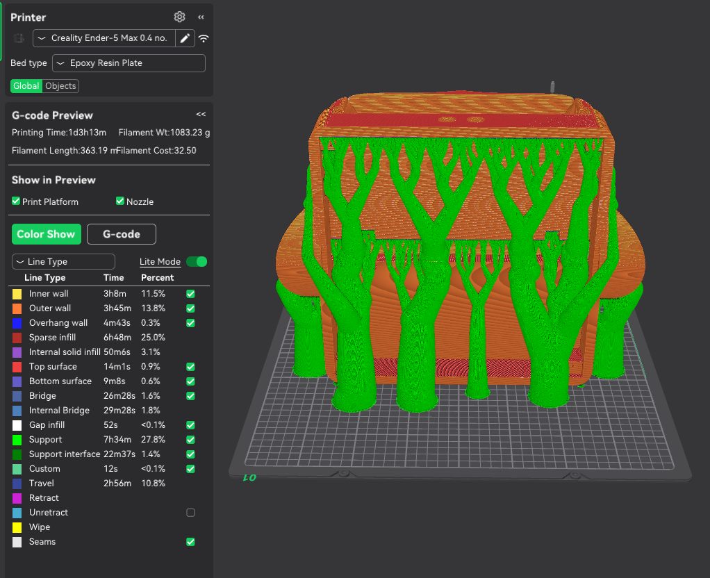
Hull in slicer with supports
FIG 1.10Hull print prep — slicer
Hull under static load
FIG 1.11Buoyancy load test
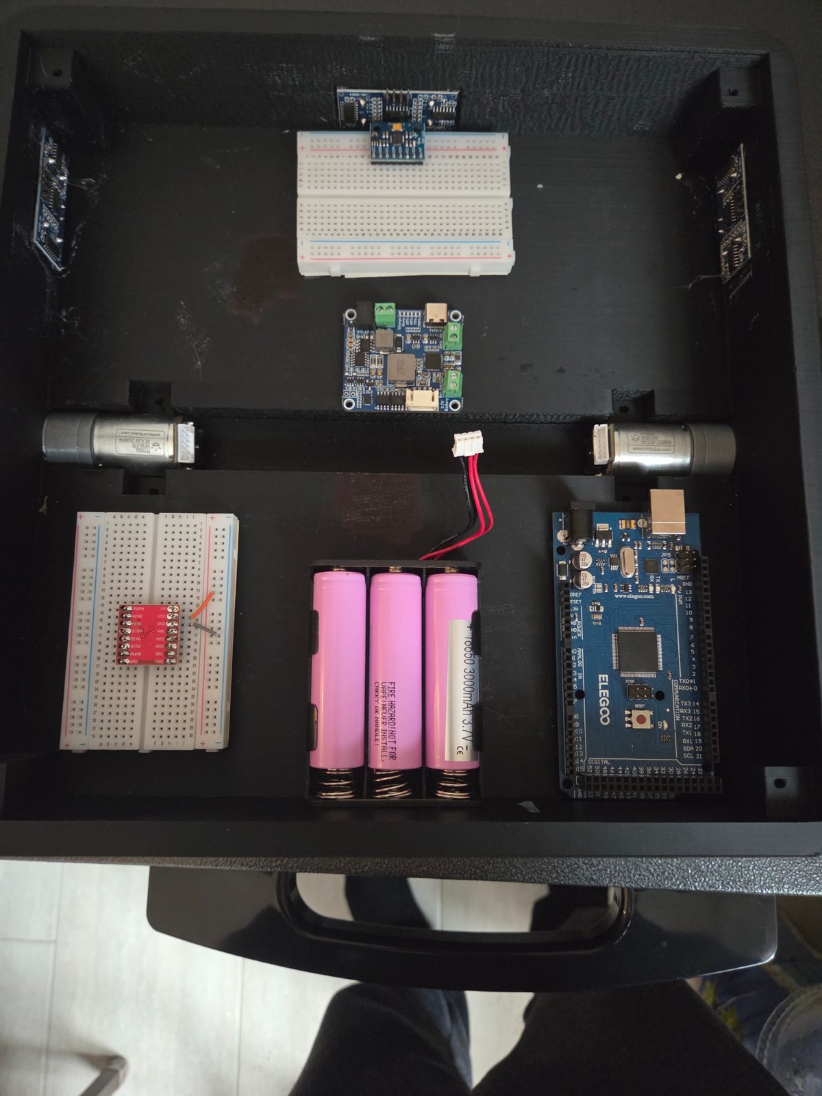
Electronics layout inside the enclosure
FIG 1.12Internal layout
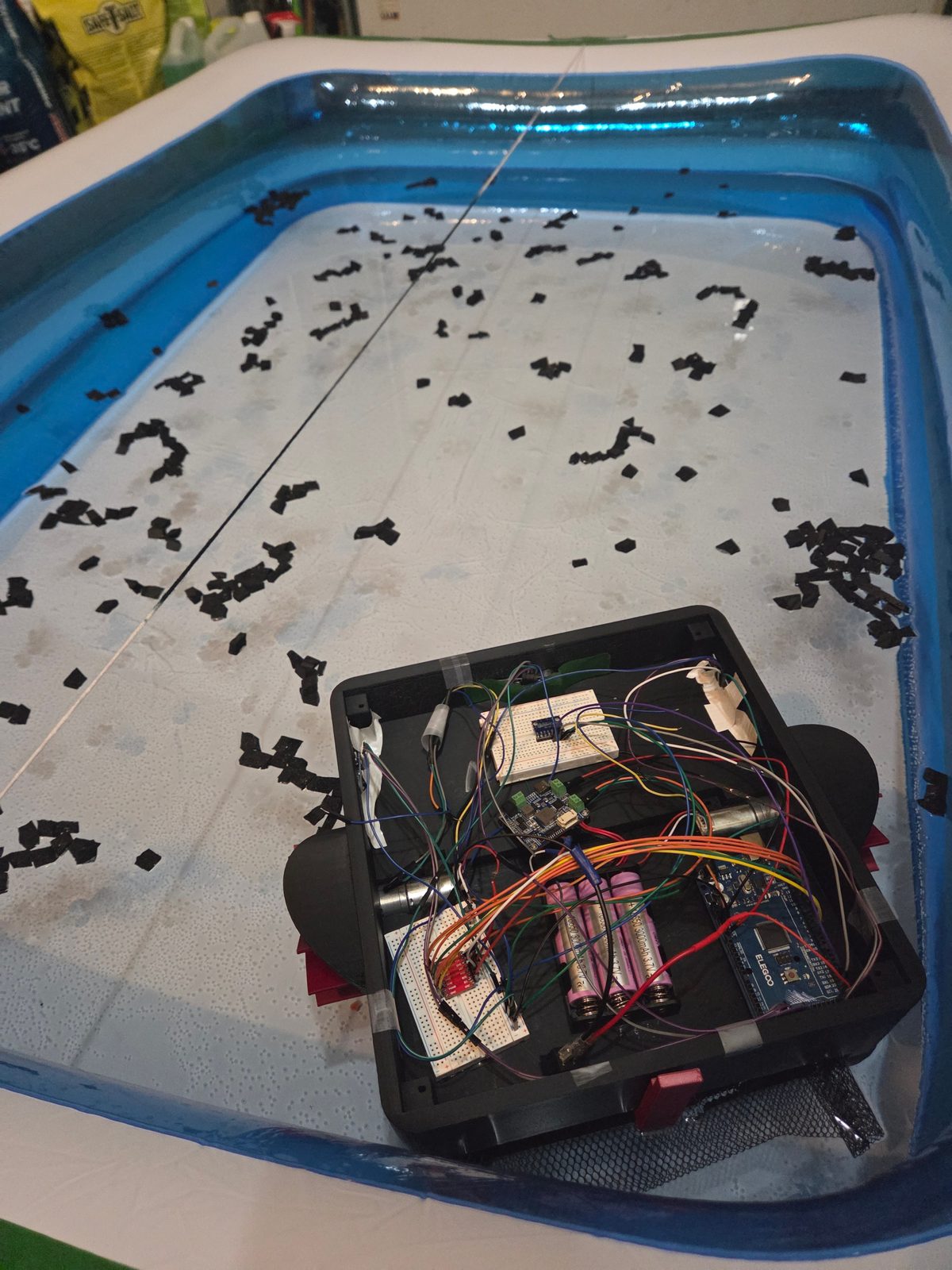
Debris collection test in water
FIG 1.13Debris collection test

Forward velocity vs motor power

Measured over 2.75 m in water — near-linear response
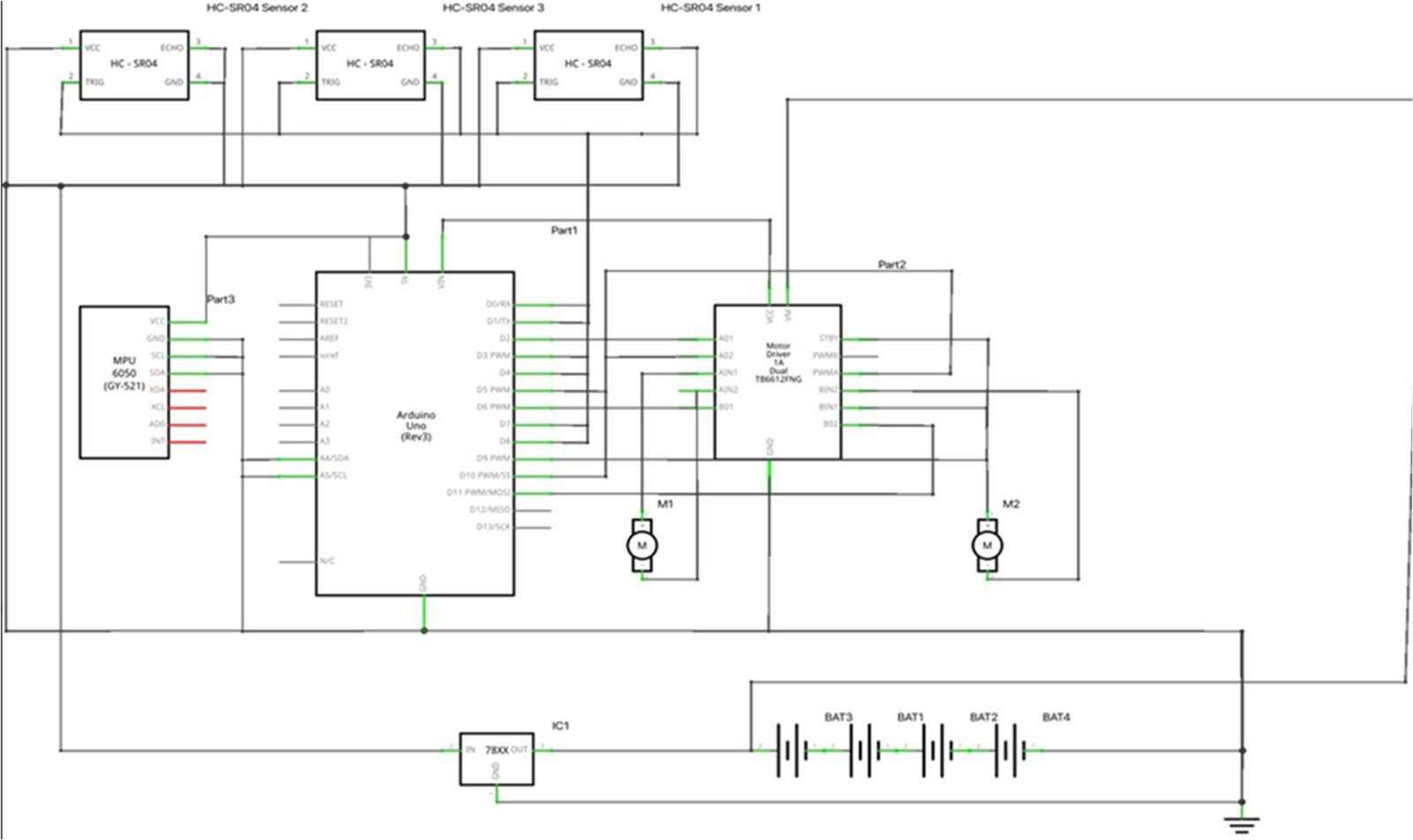
Wiring schematic
FIG 1.14Wiring schematic

Testing also showed ultrasonic ranging within 2–6% error over 10–60 cm, and reliable obstacle avoidance once the detection threshold was set at 22 cm or more.
P.02 — ROBOTICS & AUTOMATION · FALL 2025

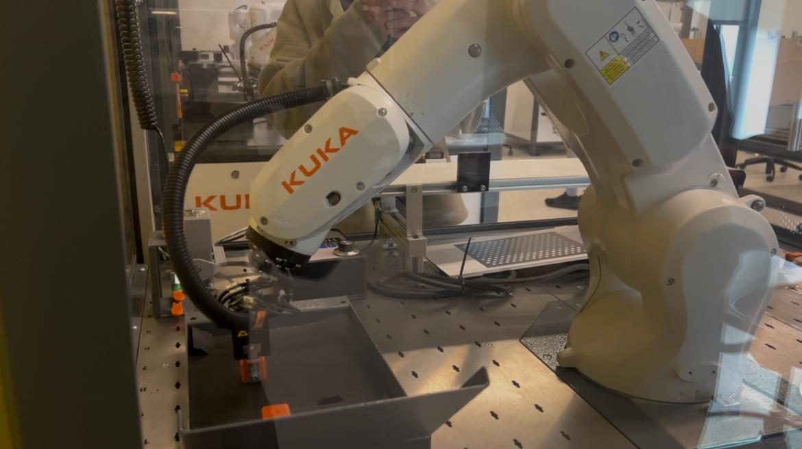
KUKA KR 4 Programming & Vision-Guided Pick-and-Place

Industrial robot programming in KRL on a KUKA KR 4 R600 AGILUS

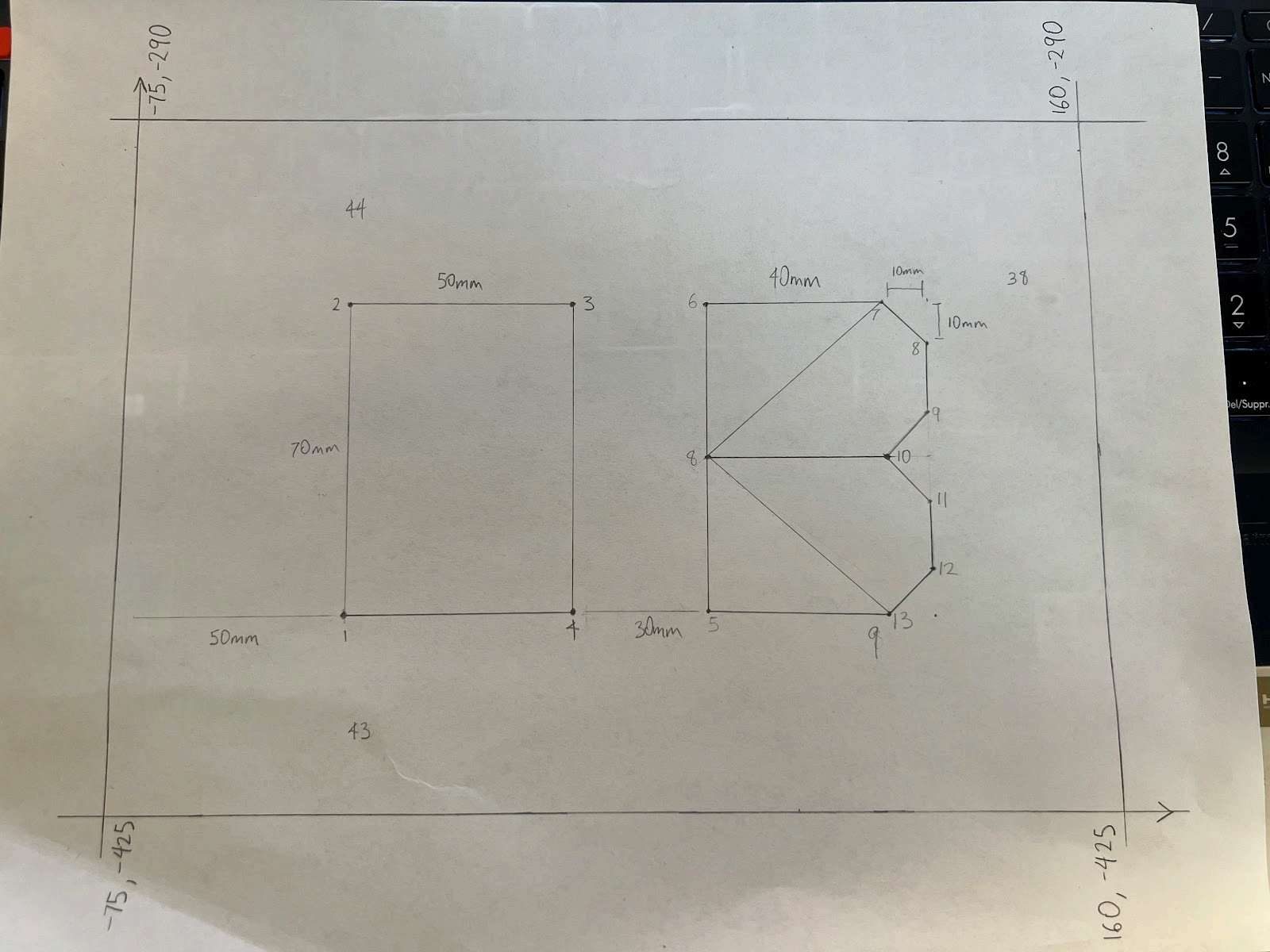
A series of lab projects programming a six-axis industrial arm. One program drives a pen through planned Cartesian waypoints using inverse-displacement calls to draw initials, with pen-up/pen-down heights and halts on unreachable poses. Another integrates the VISOR 2D vision system: the camera locates randomly placed blocks, and the robot uses the returned pose to approach from a safe height, grip, and place each part into fixed pallet positions with spline and linear motions.

KUKA KRLRobot visionInverse kinematicsPath planningWorkcell safety
  • RobotKUKA KR 4 R600 AGILUS, six-axis
  • VisionVISOR 2D camera, calibrated to the robot frame
  • MotionSpline (SPL) and linear (SLIN) moves, 250 mm safe approach height
  • TeamPair project, shared workcell
KUKA robot in workcell
FIG 2.1KR 4 in the workcell
Planned drawing path with coordinates
FIG 2.2Planned path & coordinates
Initials drawn by the robot
FIG 2.3Result drawn by the robot
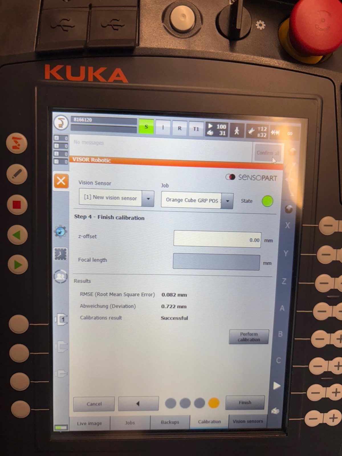
KUKA pendant showing vision calibration
FIG 2.4Vision calibration on the pendant
P.03 — FINITE ELEMENT ANALYSIS · FALL 2023

Truss & Frame FEM with Custom MATLAB Solvers

Multi-element beam & frame modelling

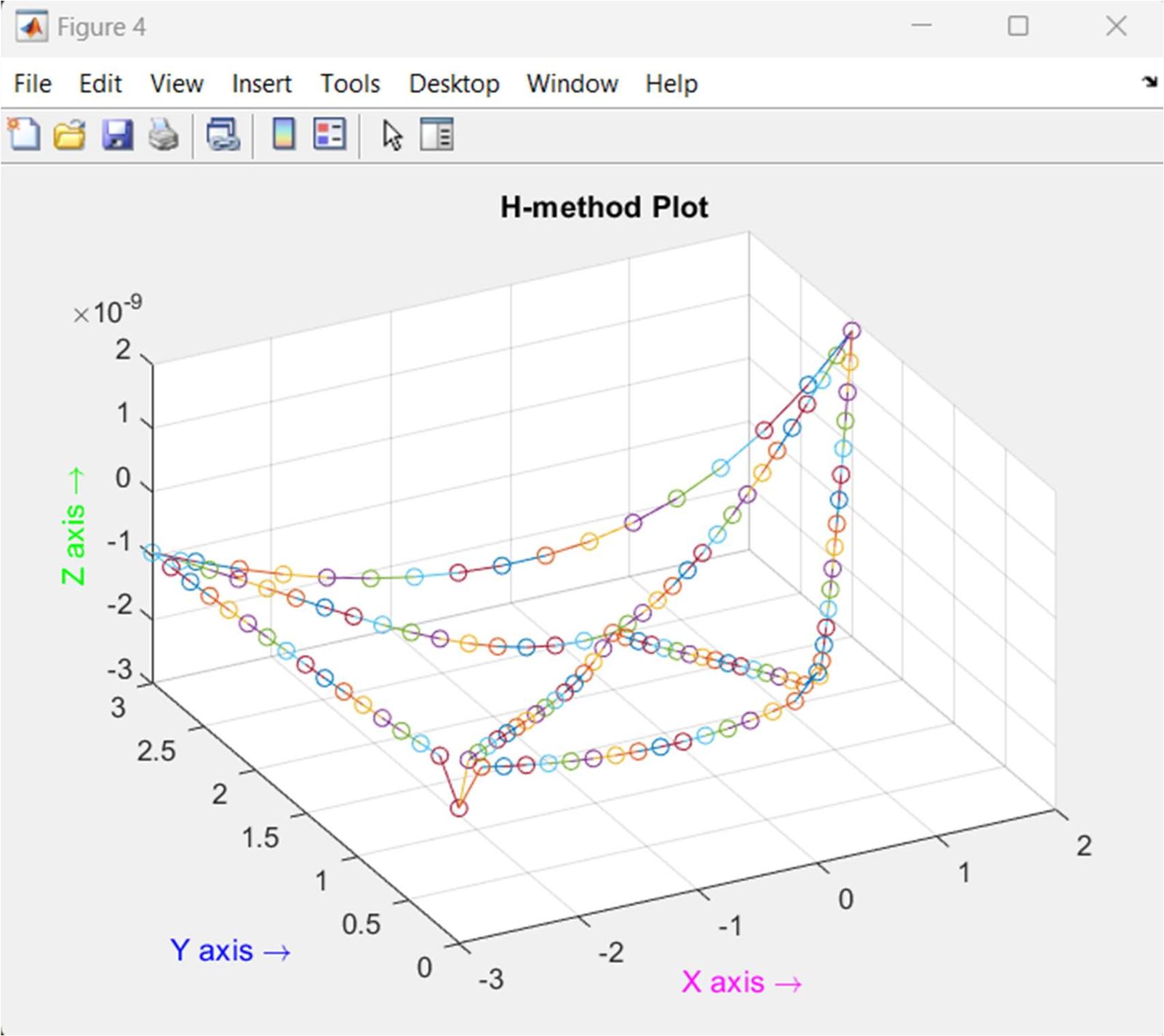
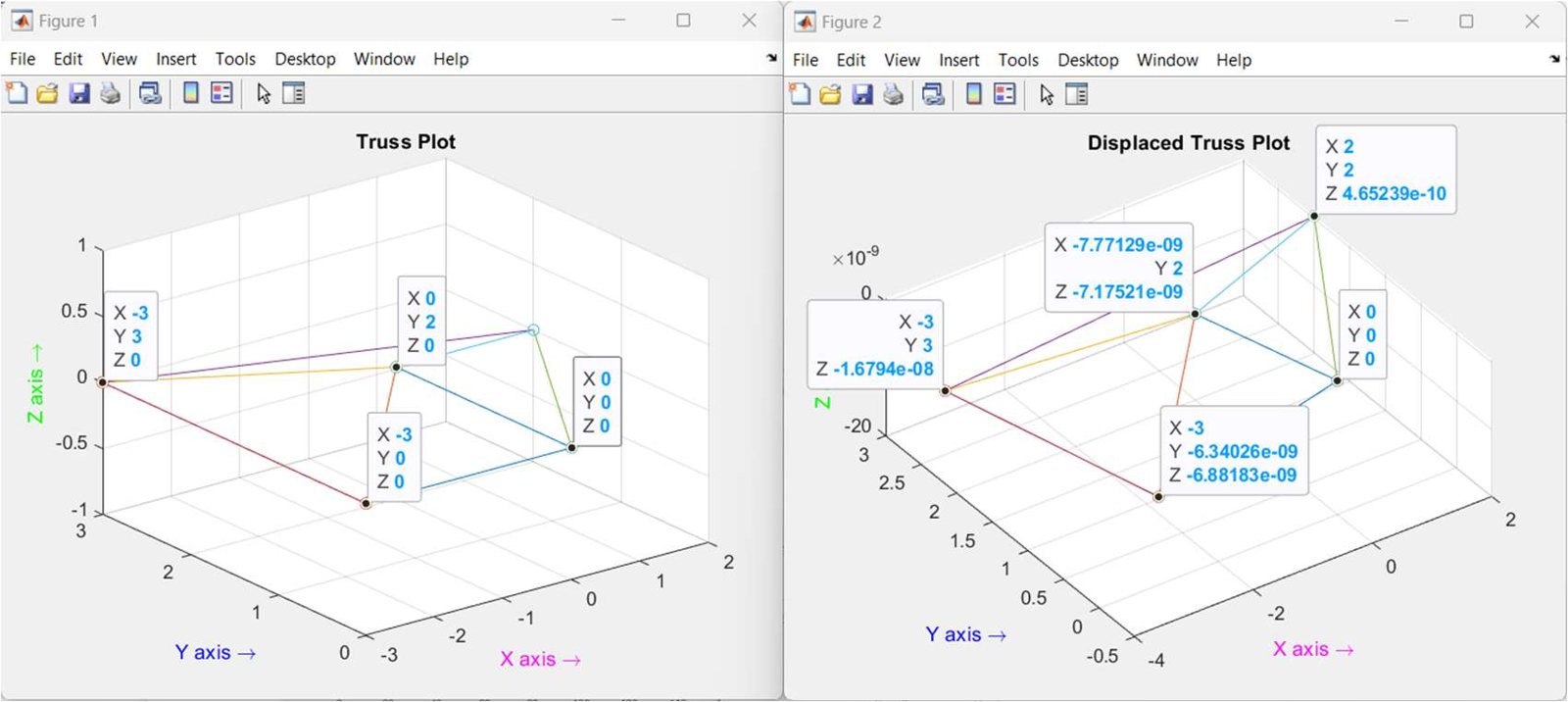
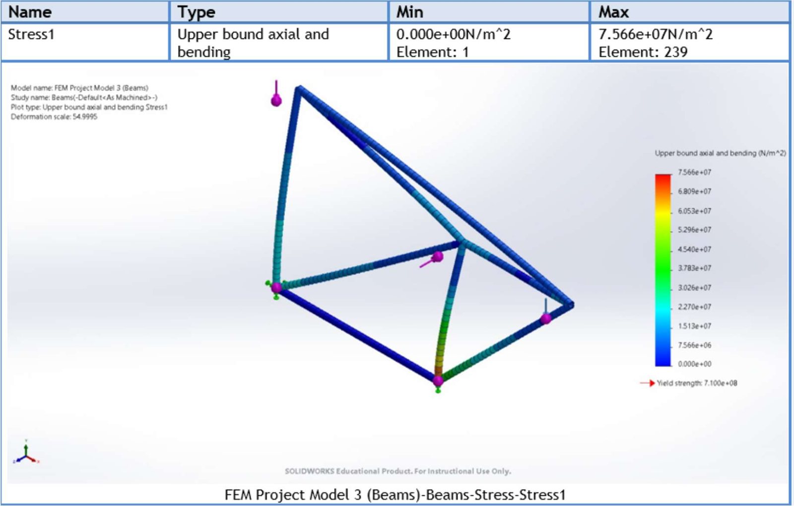
Built and validated multi-bar and beam 3D space frames two ways: in SolidWorks Simulation, and with MATLAB solvers written from scratch — assembling global stiffness matrices to solve for nodal displacements and reactions, refining meshes with the H-method, and cross-checking results between the two.

MATLABSolidWorks SimulationStiffness methodH-method refinement
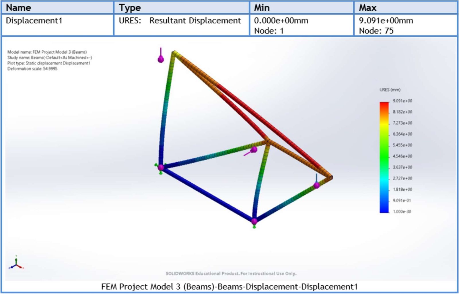
  • Max displacement9.09 mm (SolidWorks beam model)
  • Max stress75.7 MPa upper-bound axial + bending vs 710 MPa yield
  • SolversCustom MATLAB truss solver and H-method refinement solver
SolidWorks displacement plot
FIG 3.1SolidWorks displacement study
SolidWorks stress plot
FIG 3.2SolidWorks stress study
MATLAB H-method plot
FIG 3.3Custom MATLAB H-method displacement solver
MATLAB truss plots
FIG 3.4Custom MATLAB truss displacement solver
P.04 — ADDITIVE MANUFACTURING · WINTER 2024

CAD-to-STL Tessellation Study

How mesh resolution settings affect print-ready files

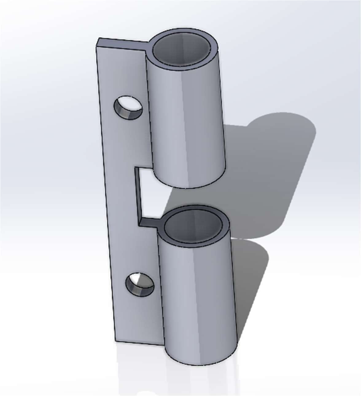
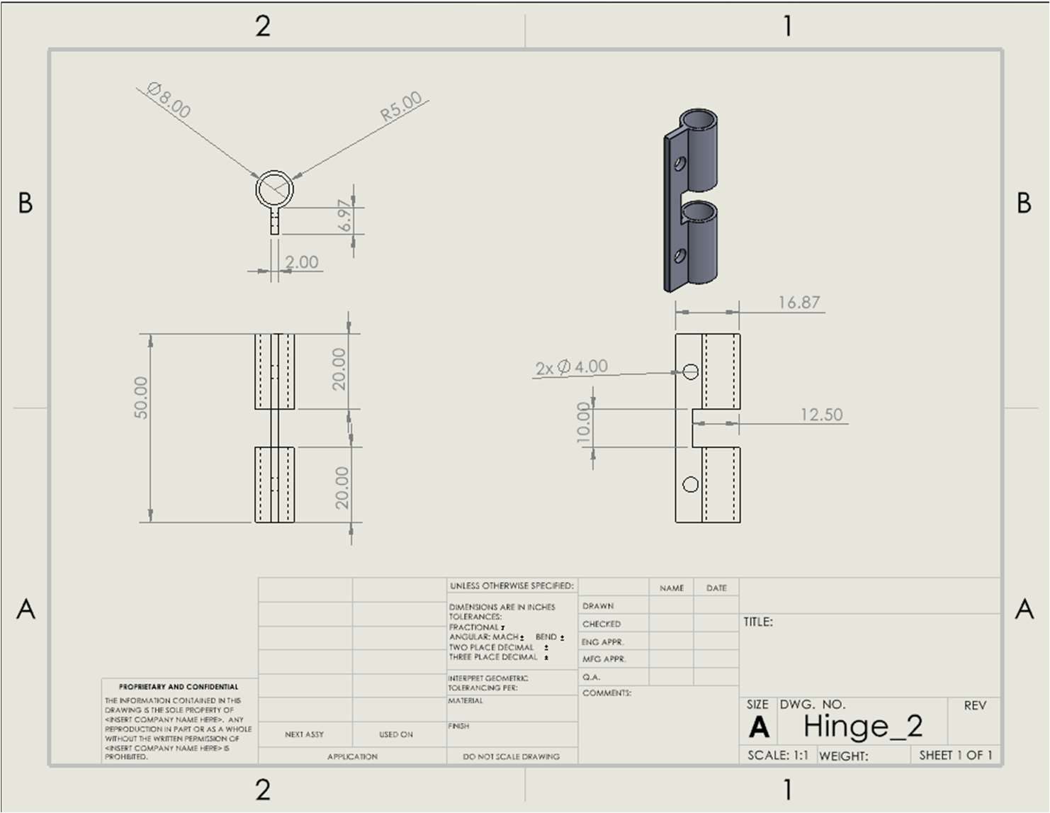
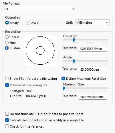
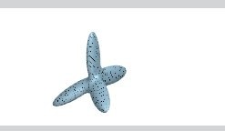
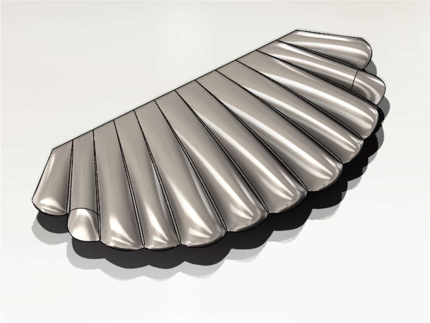
Modelled three parts of increasing complexity — a primitive pyramid, a three-part hinge mechanism sized for a 25 cm³ print envelope, and a freeform seashell — with full engineering drawings. Each was exported to STL at ten deviation/angle settings, and file size, triangle count, node count and generation time were compared to understand tessellation accuracy versus file weight.

As a bonus, I wrote a MATLAB parser that reads binary STL files byte-by-byte (normals and vertices), rebuilds the mesh, and checks the stored facet normals against recalculated ones.

SolidWorksSTL / tessellationMATLABEngineering drawings
  • FindingFile size scales with triangle count alone — facet size limits only matter through it
  • RangePyramid: 6 → 1,752 triangles across ten exports
  • CodeBinary STL reader + normal-vector verification in MATLAB
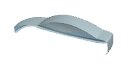
Hinge CAD model
FIG 4.1Hinge mechanism
Hinge engineering drawing
FIG 4.2Hinge part drawing
Freeform seashell CAD
FIG 4.3Freeform seashell
STL export resolution settings
FIG 4.4STL deviation & angle settings
P.05 — MECHATRONICS · WINTER 2023 · TEAM OF 5

Autonomous Robotic Wheelchair

LEGO EV3 prototype programmed in Python

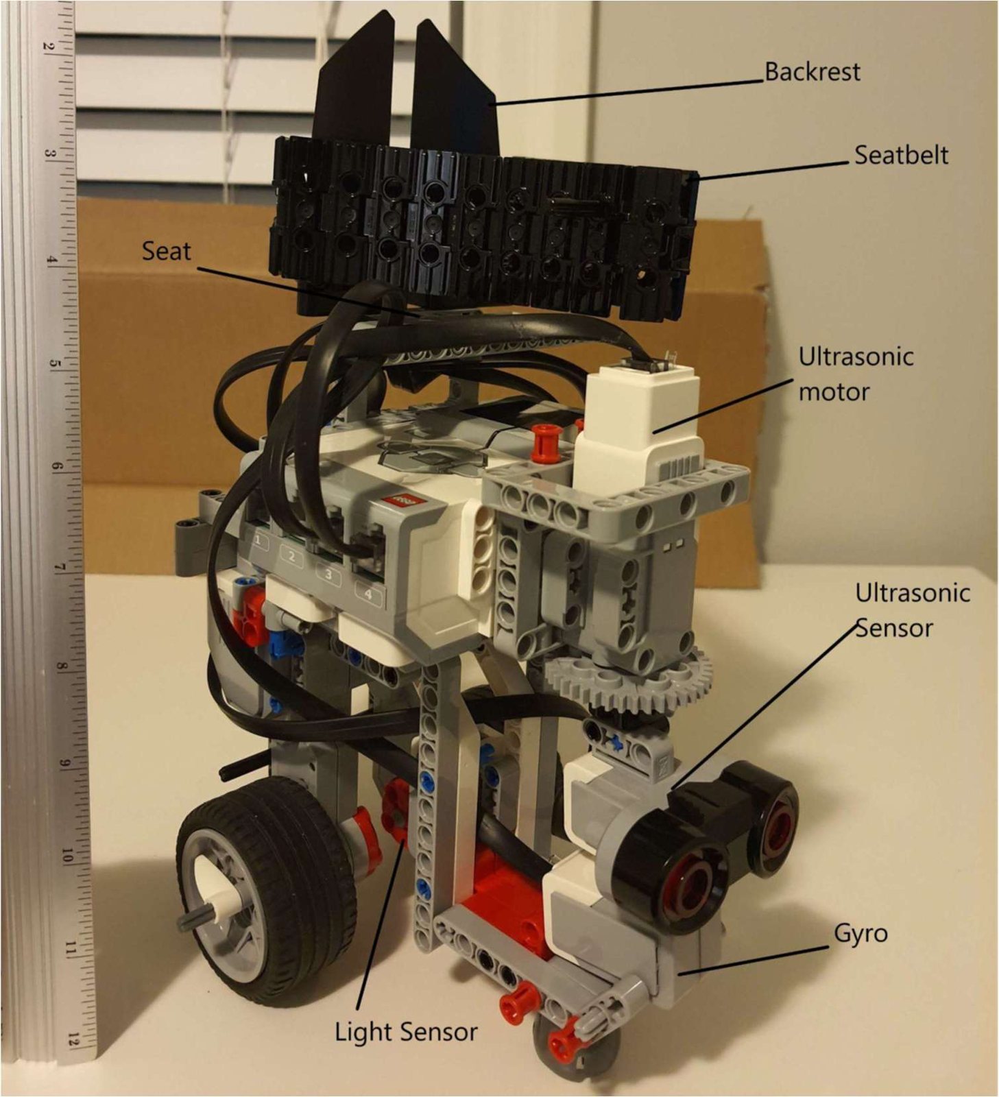
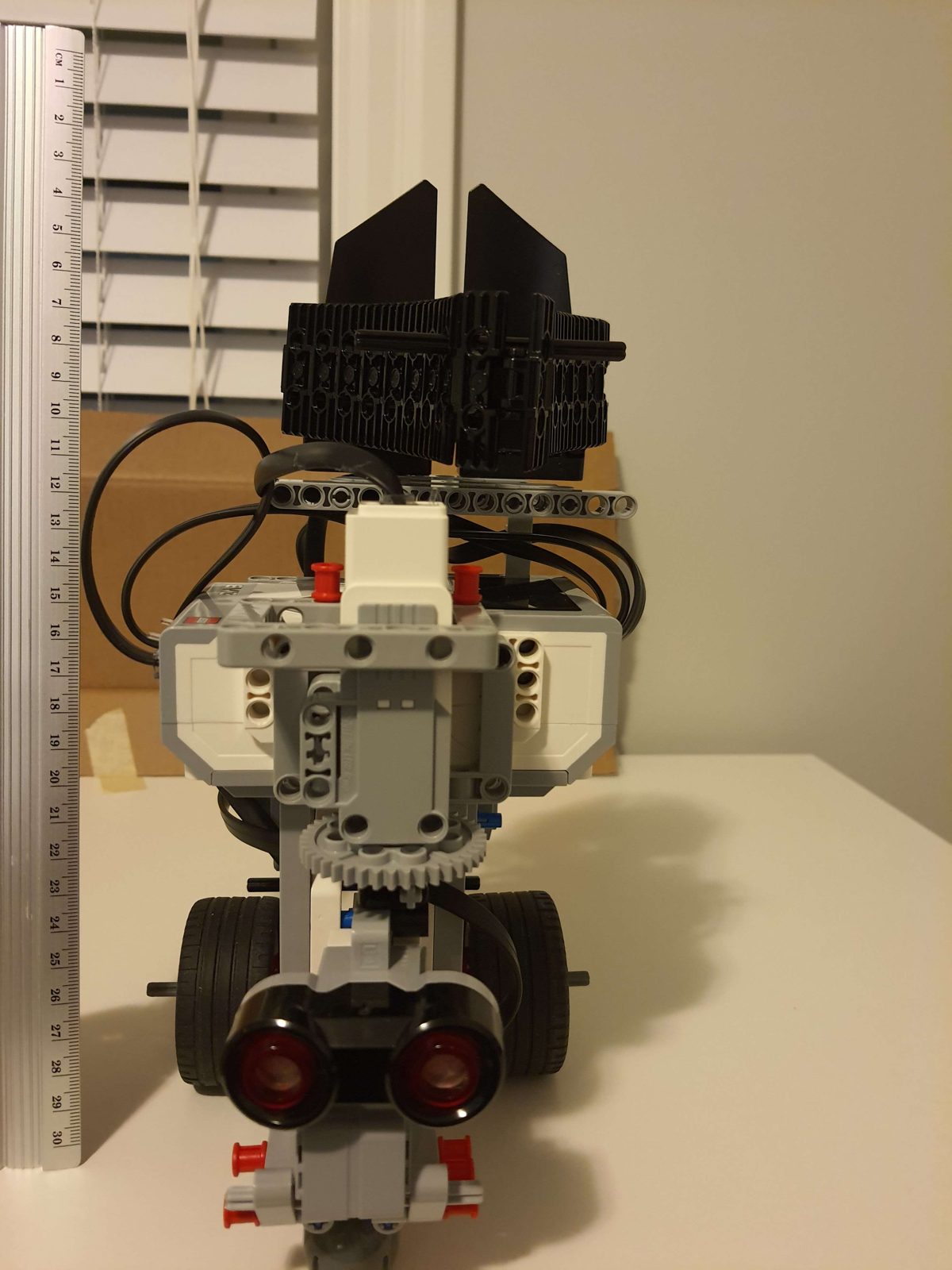
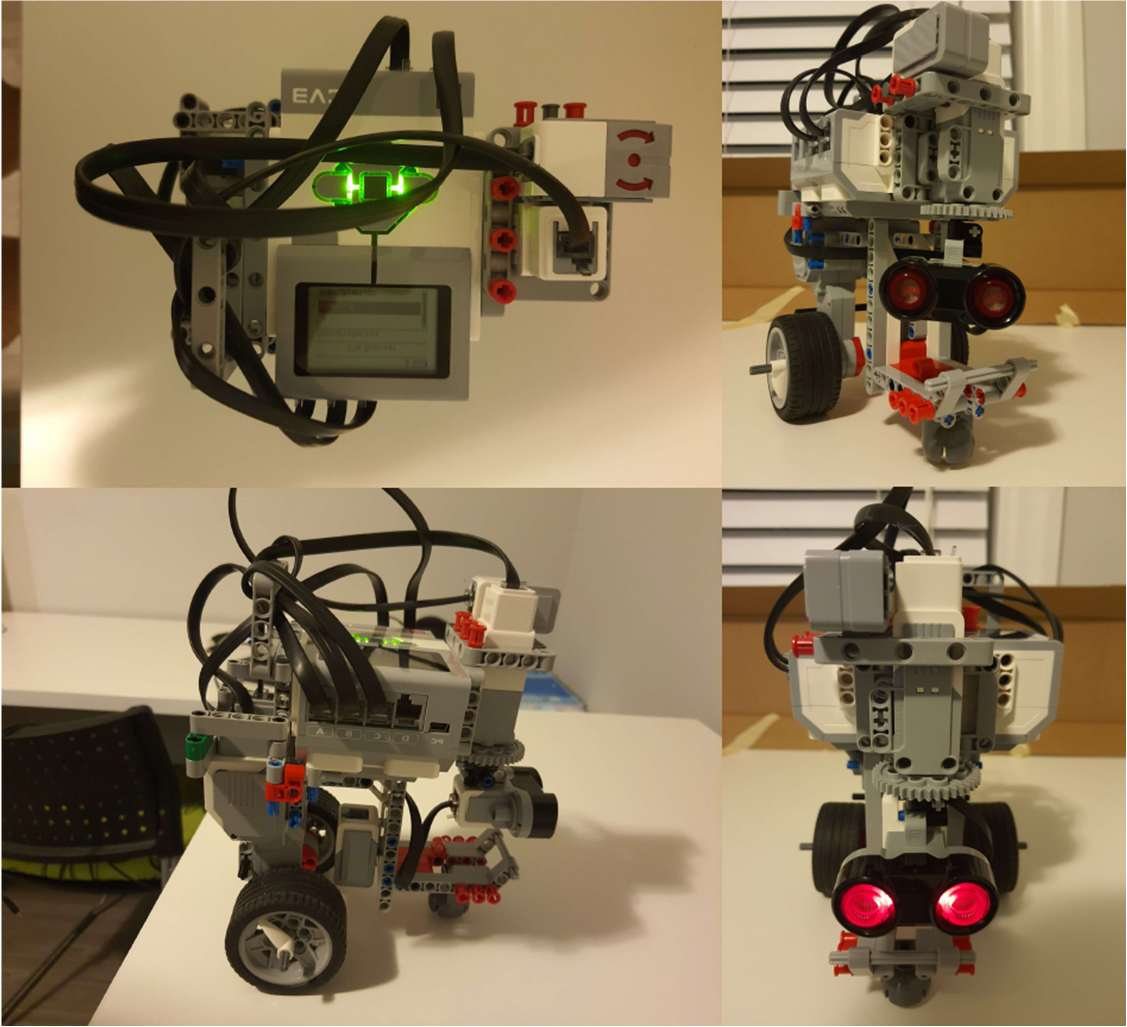
A scaled autonomous wheelchair that had to navigate a maze without touching the walls, find three points of interest, and climb a ramp. After two prototypes proved too wide and unstable, the design moved to a compact vertical layout with a lowered ultrasonic sensor, a centred gyro, and a seat with a locking seatbelt.

The control code (Pybricks MicroPython) uses a gyro-based proportional controller to hold a straight line, a servo-swept ultrasonic sensor to check for open corridors, and a light sensor to stop at each point of interest.

PythonP-controlSensor integrationIterative prototyping
  • SensorsGyro, ultrasonic on a rotating mount, light sensor
  • ControlProportional gyro correction for straight-line driving
  • IterationsThree design versions before the final build
Wheelchair robot with labelled components
FIG 5.1Final design, labelled
Front view of final design
FIG 5.2Front view
Multiview of design
FIG 5.3Multiview
P.06 — MATERIAL REMOVAL PROCESSES · WINTER 2024

CNC Milling & Metal Cutting

Hands-on machining, CAM and tooling knowledge

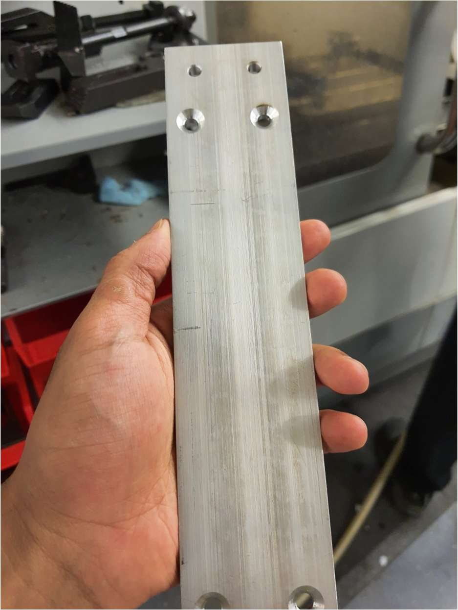
Shop time milling aluminium parts on CNC equipment, alongside Fusion 360 CAM toolpath work. To go deeper on cutting tools, I completed the Sandvik Coromant Academy Metal Cutting Technology programme and ten Mitsubishi Materials machining courses covering drilling, turning, face and end milling, tool grades and workpiece materials.

CNC millingFusion 360 CAMCutting dataTool selection
CNC-milled aluminium part
FIG 6.1CNC-milled aluminium part
P.07 — COMPUTER AIDED DESIGN · FALL 2022 · TEAM OF 4

Adjustable Driver Car Seat

Full Siemens NX model with motion simulation

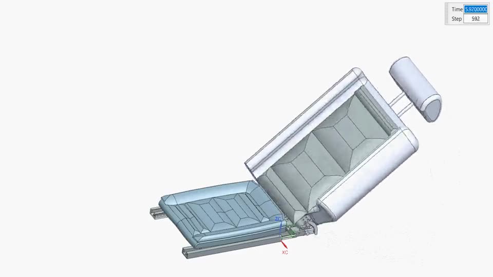
Design brief: a driver's seat for a typical sedan, with manual mechanical mechanisms to slide the seat toward or away from the steering wheel and to recline the backrest, backed by a patent and standards review, a full CAD model, motion animations and a GD&T drawing package.
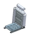
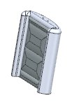
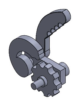
The team modelled the seat around a skeleton part, then built the slide rails and sliding bracket for fore-aft travel, a toothed one-way recliner lever with a locking gear, and the seat base, backrest, cushions and head rest. NX motion studies check each adjustment through its full range.
Siemens NXSkeleton modellingNX MotionMechanism designErgonomics
  • AdjustmentsFore-aft slide on rails; ratcheting recline
  • Model35 NX part and assembly files: brackets, gears, lever, rails, cushions
  • BriefCAD model, motion animations, GD&T drawing package, report
FIG 7.1Recline through full range
FIG 7.2Fore-aft slide on the rails
FIG 7.3One-way recliner lever and gear
Car seat assembly in Siemens NX
FIG 7.4Seat assembly
Seat back frame
FIG 7.5Seat back frame
One-way recliner lever
FIG 7.6Recliner lever concept
Seat slide rail
FIG 7.7Seat slide rail
P.08 — KINEMATICS & DYNAMICS OF MACHINES · FALL 2022 · TEAM OF 5

Crank-Driven Casement Window

Mechanism design and motion simulation in Siemens NX

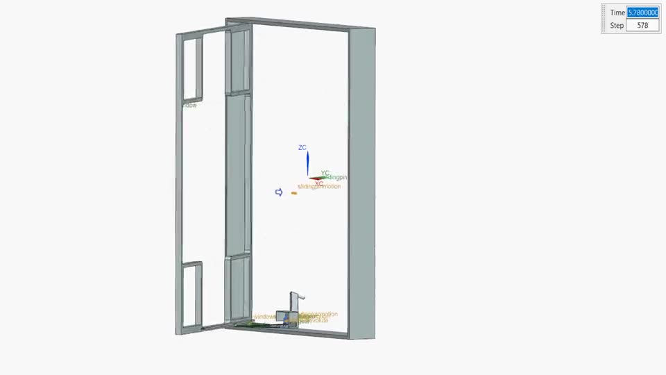
A vertical casement window that opens a full 90° outward from the sill while meeting egress code, with the mechanism hidden when closed and both faces of the glass reachable for cleaning. Early multi-link versions were too complex and fragile, so the final design was simplified to a crank, two gears and a single link.

The crank and gears are fixed in the casing, and only the link attaches to the moving sash. The team checked mobility with Kutzbach's equation and verified the motion in NX before finalizing.

Siemens NXNX MotionMobility analysisGear trainBuilding code
  • Motion0–90° outward swing driven by a hand crank
  • MechanismCrank → 2 gears → link → sash
  • ConstraintEgress code: opening > 3.77 sq ft, min 380 mm
FIG 8.1Window opening — NX motion study
Casement window frame
FIG 8.2Window frame and casing
P.09 — CONCURRENT ENGINEERING & DESIGN · FALL 2021

Aircraft Landing Gear & Walking Rickshaw Mechanism

Two team design projects with virtual and Meccano prototypes

Landing gear (team of 6): a two-wheel nose gear retracted and extended by a hydraulic actuator, designed to fold into a compartment shared and negotiated across a "super group" of teams. Delivered with a SolidWorks motion study, assembly and part drawings, and a Meccano prototype.

Walking rickshaw: an autonomous mechanical walking mechanism to pull a rickshaw, taken through concept selection into a SolidWorks motion model, a BOM drawing and a working motor-driven Meccano build.

SolidWorksMotion studyHouse of QualityConcept selectionPhysical prototyping
FIG 9.1Landing gear retraction — motion study
FIG 9.2Walking mechanism — virtual prototype
FIG 9.3Walking mechanism — Meccano prototype
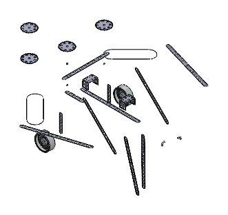
Rickshaw walking mechanism CAD
FIG 9.4Walking mechanism assembly
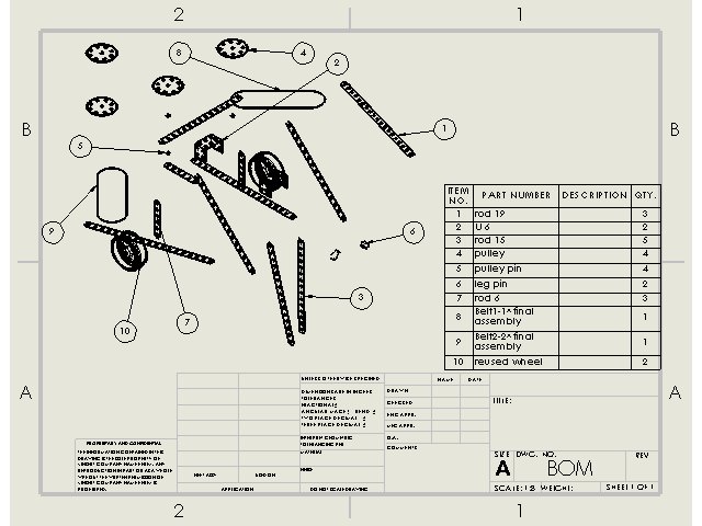
Rickshaw BOM drawing
FIG 9.5Exploded BOM drawing
Landing gear concept CAD
FIG 9.6Landing gear concept
02

CAD & animation archive

More models, drawings and motion studies from coursework, 2021–2025. Click any model to enlarge it.

Motion studies

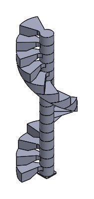
SWSpiral staircase — assembly sequence
SWFolding stair concept
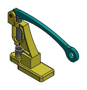
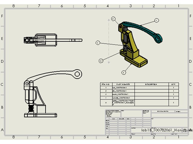
SWHand press — lever action
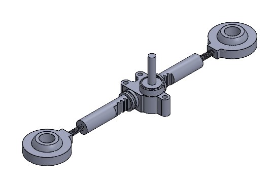
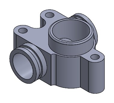
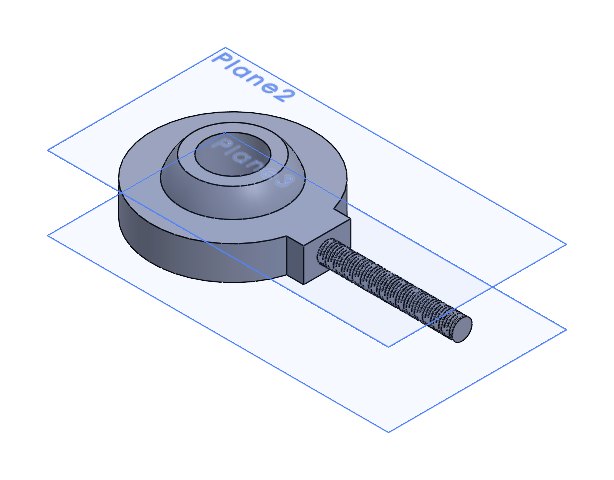
SWRack-and-pinion assembly
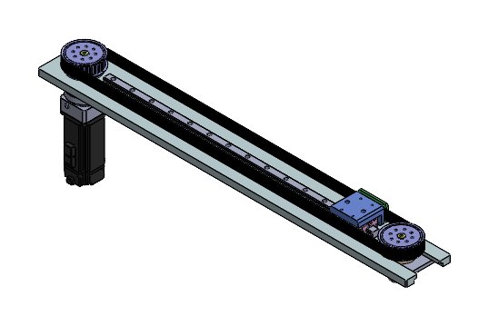
SWBelt-driven linear slide
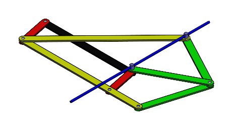
SWMulti-bar linkage (midterm)

Models & drawings

03

Skills & credentials

Design & CAD

  • SolidWorks — parts, assemblies, drawings, motion
  • Siemens NX — modelling, surfacing, NX Motion
  • Fusion 360 CAM
  • Design for FDM printing

Analysis & code

  • ANSYS CFD
  • SolidWorks & NX Simulation (FEA)
  • MATLAB — FEM solvers, simulation
  • Python, Arduino C++, KUKA KRL

Hands-on

  • Rapid prototyping & assembly
  • CNC milling
  • Sensors, motor drivers, wiring
  • Industrial robot programming

Sandvik Coromant Academy

Metal Cutting Technology diploma

March 2024

Mitsubishi Materials

Machining Technology Expert Programs — 10 courses

March 2024

Professional

EIT-eligible in all Canadian provinces

B.Eng. Mechanical, Ontario Tech University
04

Let's talk

Looking for entry-level roles in mechanical design, analysis or product development. Based in Oshawa and open to relocation.